
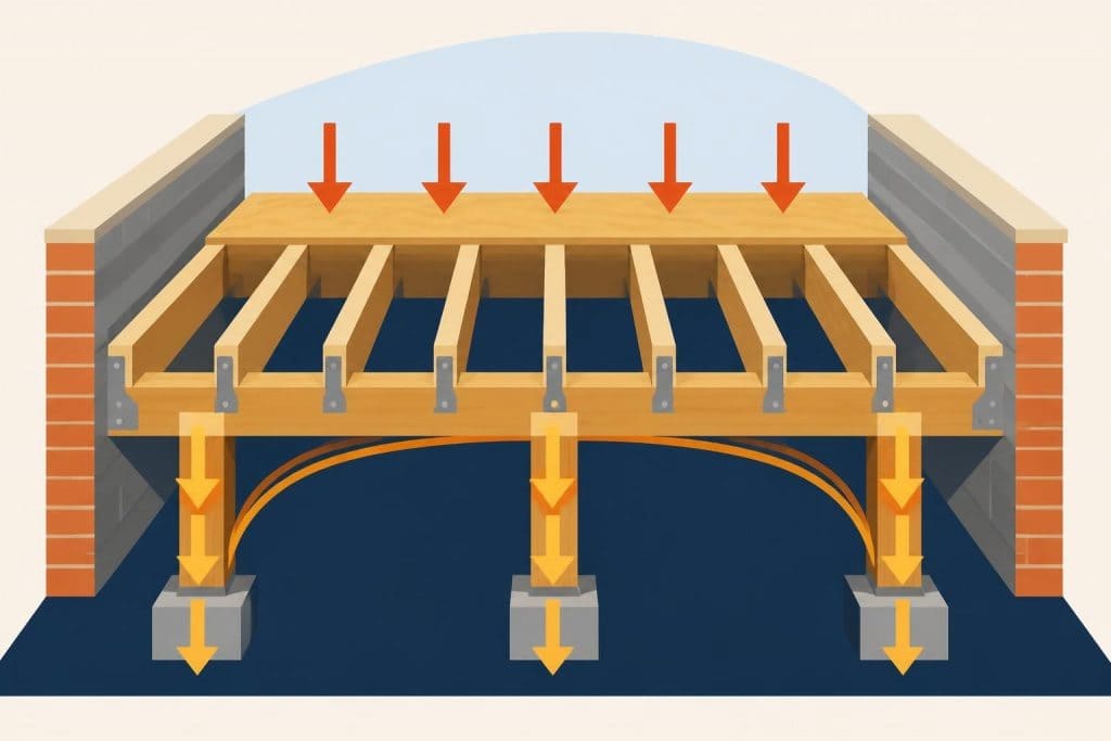
A timber floor frame forms the essential horizontal structural platform in timber frame buildings, distributing loads safely from occupants and furniture down through the building's framework to the foundations. Whether you're planning a bespoke timber structure or a standard design, understanding the principles behind timber floor frame construction ensures structural integrity, longevity, and compliance with UK building regulations. From traditional oak constructions to modern engineered timber systems, the timber floor frame represents a critical junction where craftsmanship meets contemporary engineering standards.
Understanding Timber Floor Frame Construction
The timber floor frame comprises several interconnected components working together to create a stable, level platform. At its core, the system includes joists, beams, noggins, and various fixings that transfer vertical and horizontal loads throughout the structure.
Primary Structural Components
A typical timber floor frame consists of joists running parallel at regular centres, supported by loadbearing walls or beams. These joists represent the primary structural members, spanning between supports and carrying the floor decking above.
Key components include:
- Joists: horizontal timbers spaced at 400mm or 600mm centres
- Trimmer joists: reinforced members around openings
- Noggins: lateral bracing between joists
- Joist hangers: metal fixings connecting joists to beams
- Rim joists: perimeter framing members
The structural integrity of timber frame buildings depends heavily on proper floor frame installation. Each component must be sized appropriately for the anticipated loads and span distances, whilst connections require careful attention to ensure adequate load transfer.
Load Distribution Principles
Understanding how loads travel through a timber floor frame proves essential for proper design. Dead loads comprise the weight of the structure itself, including floor decking, joists, and any permanent fixtures. Live loads account for furniture, occupants, and moveable items.
| Load Type | Typical Value | Design Consideration |
|---|---|---|
| Dead Load | 0.5-1.0 kN/m² | Floor construction weight |
| Live Load | 1.5-2.0 kN/m² | Domestic occupancy |
| Point Loads | Variable | Concentrated equipment |
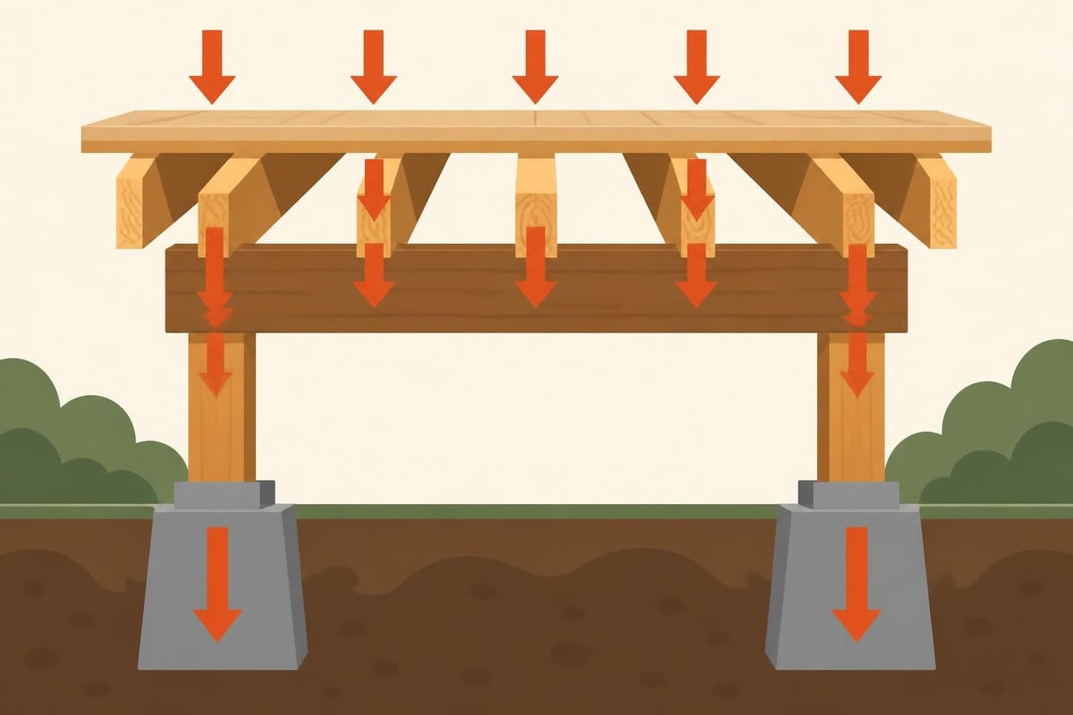
These loads transfer vertically through the joists to supporting beams or walls, then downward through posts or studs to the foundations. Proper spacing and sizing calculations ensure deflection remains within acceptable limits, preventing bouncy floors and ensuring occupant comfort.
Design Standards and Regulations
Timber floor frame design in the UK must comply with strict building regulations and industry standards. These requirements ensure structural safety, fire resistance, and acoustic performance meet minimum thresholds.
UK Building Regulations Compliance
Part A of the Building Regulations addresses structural safety, requiring timber floor frames to support all anticipated loads without excessive deflection or failure. The Timber Frame Engineering Council standards provide comprehensive guidance for engineers designing timber floor systems.
Designers must consider:
- Structural adequacy under maximum loading conditions
- Deflection limits ensuring floors don't feel bouncy
- Vibration serviceability preventing uncomfortable movement
- Fire resistance maintaining integrity during fire exposure
- Acoustic separation between different occupancies
The ISO 24323:2023 standard specifically addresses vibrational serviceability of timber floors, providing assessment methods for both light frame and mass timber systems. This proves particularly relevant for modern open-plan designs where long spans can create vibration challenges.
Joist Sizing and Span Tables
Proper joist sizing depends on span distance, spacing, and timber species. UK building control relies on span tables from BS 5268 or manufacturer-specific engineered timber specifications.
For typical domestic applications using C16 or C24 graded timber:
| Joist Size | Maximum Span (400mm centres) | Maximum Span (600mm centres) |
|---|---|---|
| 47x150mm | 3.05m | 2.45m |
| 47x175mm | 3.65m | 2.94m |
| 47x200mm | 4.19m | 3.37m |
| 47x225mm | 4.69m | 3.78m |
These figures assume standard domestic loading and C16 timber. Higher grade timber or engineered products allow longer spans with smaller sections, offering design flexibility whilst maintaining structural performance.
Construction Methods and Installation
Installing a timber floor frame requires precision, proper sequencing, and attention to detail. Whether constructing ground floors or upper storeys, the methodology remains broadly similar whilst accounting for specific contextual requirements.
Ground Floor Systems
Ground floor timber frames typically sit above either concrete slabs or suspended void spaces. The integration between substructure and timber floors requires careful detailing to manage moisture, ventilation, and thermal performance.
Installation sequence:
- Install DPC (damp proof course) on supporting walls
- Position wall plates level and square
- Mark joist centres accurately
- Install joists using appropriate hangers or bedding
- Add noggins at mid-span for lateral stability
- Check levels across entire floor area
- Install services before decking
Ventilation beneath suspended ground floors prevents moisture accumulation that could lead to timber decay. Building regulations specify minimum ventilation rates based on floor void volume and perimeter length.
Upper Floor Installation
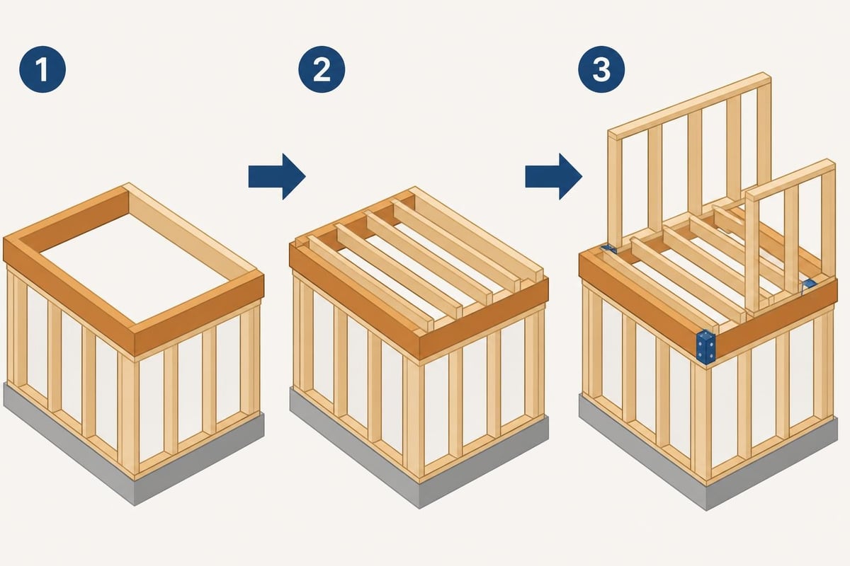
Upper floors in timber frame buildings connect directly to wall frames, creating a platform for the storey above whilst providing lateral restraint to walls below.
The rim joist or ribbon board runs along the perimeter, sitting on the wall top plate. Joists then connect to this perimeter member using joist hangers or direct nailing, depending on design preferences and structural requirements.
Material Selection and Sustainability
Choosing appropriate materials for timber floor frames impacts both structural performance and environmental credentials. Modern construction increasingly emphasises sustainable sourcing and lifecycle considerations.
Timber Species and Grades
Softwood species dominate UK timber floor frame construction, with European redwood and whitewood being most common. These arrive graded to C16 or C24 strength classes, indicating their structural capacity.
For traditional builds and premium projects, oak provides exceptional durability and aesthetic appeal. Sustainably sourced oak timber offers superior longevity compared to softwood alternatives, though higher material costs require careful project budgeting.
Common timber options include:
- C16 Graded Softwood: economical, suitable for standard applications
- C24 Graded Softwood: higher strength, allows longer spans
- Engineered Timber (I-joists): consistent performance, reduced material usage
- Oak: traditional choice, exceptional durability and appearance
- LVL (Laminated Veneer Lumber): manufactured beams for long spans
Engineered Timber Products
Engineered timber products offer advantages over solid sawn timber, including dimensional stability, consistent strength properties, and efficient material use. I-joists, for instance, use less timber whilst achieving equivalent or superior structural performance.
Research into timber-concrete composite systems demonstrates how combining materials can optimise floor performance. These hybrid approaches prove particularly valuable in renovation projects or where exceptional span capabilities are required.
Acoustic and Thermal Performance
Beyond structural adequacy, modern timber floor frames must deliver acceptable acoustic insulation and thermal efficiency. These performance criteria significantly impact occupant comfort and building regulatory compliance.
Sound Insulation Strategies
Airborne and impact sound transmission through floors causes significant disturbance in multi-occupancy buildings. Effective sound insulation requires a multi-layered approach addressing different transmission paths.
| Strategy | Airborne Improvement | Impact Improvement |
|---|---|---|
| Increased joist depth | Moderate | Low |
| Mineral wool between joists | High | Low |
| Resilient ceiling bars | High | Moderate |
| Floating floor finish | Low | High |
| Mass layer in ceiling | High | Moderate |
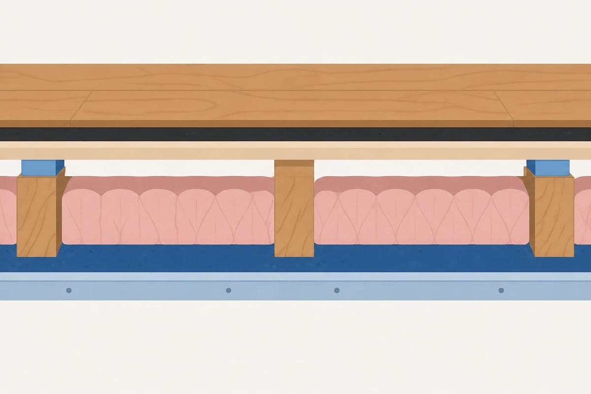
The floor deck itself, typically 18mm or 22mm tongued and grooved chipboard or OSB, forms the first barrier. Below this, mineral wool insulation between joists absorbs sound energy. Independent ceiling construction prevents vibration transfer from floor to ceiling finish.
Thermal Bridging Considerations
Where timber floor frames intersect external walls, thermal bridging can occur unless properly detailed. Continuous insulation layers and appropriate junction detailing prevent heat loss and condensation risk.
Ground floors require particular attention, with insulation placed either beneath the floor deck or below the concrete slab in beam-and-block systems. Upper floors separating heated and unheated spaces similarly require insulation to meet Building Regulations Part L requirements.
Common Challenges and Solutions
Timber floor frame construction presents various challenges that experienced builders anticipate and address through proper planning and execution. Understanding these potential issues enables proactive solutions rather than reactive fixes.
Deflection and Vibration Control
Excessive deflection creates bouncy floors that feel unstable, even when structurally adequate. Modern open-plan layouts with fewer internal walls provide less support, exacerbating this tendency.
Solutions include:
- Specifying deeper joists than minimum requirements
- Reducing joist spacing from 600mm to 400mm centres
- Installing strongbacks or strutting at closer centres
- Using engineered timber products with superior stiffness
- Adding supporting beams to reduce effective spans
The 2024 Wood Frame Construction Manual provides detailed guidance on calculating deflection limits and selecting appropriate joist sizes for various loading scenarios.
Moisture Management
Timber exposed to moisture risks decay, dimensional movement, and structural degradation. Effective moisture management starts during construction and continues throughout the building's life.
Protection strategies involve:
- Storing timber off ground and under cover before installation
- Installing DPC barriers between timber and masonry
- Providing adequate ventilation in floor voids
- Ensuring building envelope weather-tightness during construction
- Specifying preservative-treated timber in high-risk locations
Recent research on engineered timber reusability after moisture exposure highlights the importance of understanding how moisture affects long-term structural integrity, particularly relevant for sustainable construction practices.
Integration with Building Services
Modern buildings require extensive services distribution, with timber floor frames often accommodating pipework, electrical cables, ventilation ducts, and underfloor heating systems.
Service Routing Principles
Running services through floor frames requires careful planning to avoid compromising structural performance. Holes drilled through joists must follow specific rules regarding location and size.
Standard drilling guidelines specify:
- Maximum hole diameter: 0.25 times joist depth
- Hole location: within middle third of span
- Minimum distance from support: 3 times joist depth
- Minimum edge distance: 3 times hole diameter
- No holes in proximity to notches
Notches cut into joist tops or bottoms create stress concentrations and reduce load capacity. Where unavoidable, notches should occur near supports rather than mid-span, with depth limited to 0.125 times the joist depth.
Underfloor Heating Compatibility
Timber floor frames accommodate underfloor heating systems, though thermal properties differ from concrete slabs. Water-based systems require appropriate floor finishes that conduct heat effectively whilst protecting pipework from point loads.
Electric mat systems prove simpler to install within timber floors, sitting between the structural deck and floor finish. Insulation below the joists ensures heat flows upward into rooms rather than being lost to voids or rooms below.
Quality Assurance and Inspection
Ensuring timber floor frame quality requires systematic inspection at critical construction stages. Building control inspections verify compliance with approved drawings and building regulations, but project-specific quality checks prove equally important.
Pre-Installation Checks
Before installation begins, verify timber delivery matches specifications regarding species, grade, dimensions, and moisture content. Timber with excessive moisture content will shrink as it dries, potentially causing squeaking floors and nail pops.
Inspection checklist includes:
- Confirming timber grade stamps match specifications
- Measuring moisture content (should be below 20% for framing)
- Checking for splits, warping, or damage
- Verifying joist hanger and fixing supply
- Ensuring support surfaces are level and true
Installation Verification
During installation, regular checks ensure work proceeds according to plan. Professional timber framing specialists employ rigorous quality control processes throughout construction.
Critical inspection points include:
- Joist spacing accuracy and consistency
- Proper hanger installation and fixing
- Noggins installed at specified centres
- Level and flatness across floor area
- Correct treatment of openings and trimmers
- Service penetrations within acceptable limits
Future Developments in Timber Floor Systems
Timber floor frame technology continues evolving, driven by sustainability imperatives, performance expectations, and manufacturing innovations. Understanding emerging trends helps inform current design decisions whilst anticipating future capabilities.
Mass Timber Applications
Cross-laminated timber (CLT) and other mass timber products increasingly feature in UK construction projects. These panel systems combine structural and finished floor surfaces in single elements, accelerating construction whilst delivering excellent acoustic and fire performance.
Mass timber floors integrate particularly well with raised eaves buildings and contemporary architectural designs, offering visual warmth alongside technical performance.
Digital Design Integration
Computational design tools increasingly influence timber floor frame planning, with advanced floor plan generation methods optimising layouts for material efficiency and structural performance. Building Information Modelling (BIM) enables precise coordination between structural frames, services, and finishes before construction begins.
Prefabrication benefits from digital precision, with floor cassettes manufactured off-site to exact specifications then rapidly installed on site. This approach reduces weather exposure, improves quality control, and accelerates project programmes.
Timber floor frame construction combines traditional building principles with modern engineering standards to create durable, comfortable living platforms. From material selection and structural design through to installation details and performance optimisation, each decision impacts the finished building's quality and longevity. Whether you're planning a traditional oak frame garage or a contemporary timber dwelling, expert guidance ensures your floor frames meet both regulatory requirements and performance expectations. Acorn to Oak Framing brings decades of specialist timber framing experience to projects across the UK, combining traditional craftsmanship with contemporary design techniques to deliver exceptional structures tailored to your specific requirements.


